Failure Reason of Ceramic Capacitors
1. Ceramic chip capacitor failure caused by external force
(1) Because the ceramic chip capacitor is brittle and has no pin, it is greatly affected by the force. Once it is affected by the external force, the internal electrode is easy to break, resulting in the failure of the ceramic chip capacitor. As shown in Figures below, the capacitor end of ceramic patch is broken or damaged due to any external force. For example, in the process of mechanical assembly, the printed circuit board assembly is installed in the box, and the electric driver is used for assembly. At this time, the mechanical stress of the electric driver is easy to disconnect the capacitor. 

(2) Due to the quality problem of poor bonding force of ceramic chip capacitor end (body and electrode), the metal electrode is easy to fall off through the process of welding, warm punching, debugging and other external forces, that is, the body and electrode are separated, as shown in Figure as below.
 2. Failure caused by improper welding operation
(1) It is very common that the thermal shock of ceramic chip capacitor caused by improper manual welding or rework of electric iron.
When welding, there will be thermal shock. If the operator contacts the tip of the soldering iron directly with the electrode of the capacitor, the thermal shock will cause the micro crack of the ceramic chip capacitor body, and the ceramic chip capacitor will fail after a period of time. In principle, the SMT should be welded by hand. Multiple welding, including rework, will also affect the solderability of the chip and the resistance to welding heat, and the effect is cumulative, so it is not suitable for the capacitor to be exposed to high temperature for many times
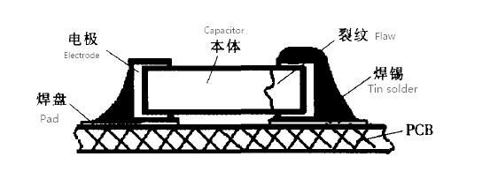
(2) The tin on both ends of the capacitor is asymmetric during welding.
When welding, the tin on both ends of the capacitor is asymmetric, as shown in below figure.
The tin on both ends of the capacitor is asymmetric. When the capacitor is subjected to external force or stress screening test, the ceramic patch will be seriously affected due to excessive soldering. The capacitor's ability to resist mechanical stress will lead to cracking of the body and electrode and failure.
(3) Too much solder
The factors related to the degree of mechanical stress of multilayer ceramic chip capacitor on PCB include the material and thickness of PCB, the amount of solder and the position of solder. Especially, too much solder will seriously affect the ability of chip capacitor to resist mechanical stress, resulting in capacitor failure.
3. Capacitor failure caused by unreasonable pad design
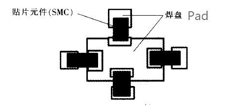
(1) The design of the pad is unreasonable, as shown in below Figure, when there is a hole in the pad. Solder will lose (there is such design phenomenon in the product), which causes welding defects due to the asymmetry of solder at both ends of capacitor. At this time, stress screening or external force will be conducted. The stress released at both ends of ceramic chip capacitor will easily cause cracking and failure.

(2) Another pad design is shown in below Figure. When using on-line welding, the size of pads at both ends of the capacitor is different or asymmetric (this design phenomenon exists in the product), the amount of solder paste printed is quite different. The small pad has a fast response to temperature, and the solder paste on it melts first. Under the action of solder paste tension, the component is straightened up, resulting in "upright" phenomenon or solder asymmetry, causing capacitor failure. One end of several ceramic chip capacitors share a large pad. If one capacitor at the common end needs to be repaired or one of the capacitors fails and needs to be replaced, one end of the other components will also experience a thermal shock, and the capacitor is prone to failure.
4. Failure caused by high and low temperature impact test
During the test, the thermal expansion coefficient (CTE) of PCB, MLCC end electrode and ceramic dielectric is small, and the chip capacitor is subjected to certain thermal stress due to the rapid change of cold and hot. The body (ceramic) and electrode (metal) of SMC produce stress cracks, which lead to the failure of SMC.
5. Failure caused by mechanical stress
Improper operation of the printing plate in the assembly process will cause mechanical stress, which will lead to capacitor rupture, and the pad is designed near the screw hole, which is easy to cause mechanical damage during assembly. This kind of damage makes the crack expand further in the temperature shock test, which leads to the capacitor failure. It can be seen from the structure that MLCC can withstand large compressive stress, but its bending resistance is poor. Any operation that may produce bending deformation during capacitor assembly will lead to component cracking.